Arrangement of Axes and Drive System
In addition to these there are a number of additional axes in the model that do not necessarily have corresponding axes in the original. The picture below shows top view of the machine with the main drive crank removed. The front of the machine is at the bottom in this picture.
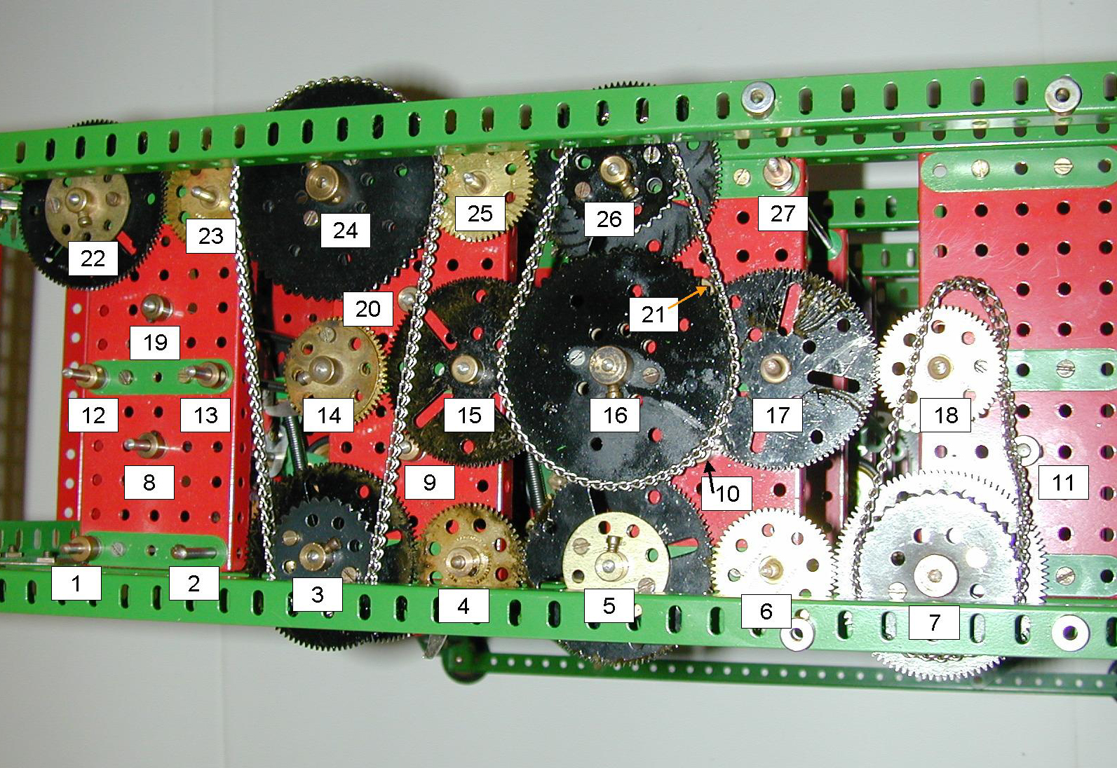
If you click on the picture above, you should get a larger image, annotated to identify each of the axes. The numbers on the picture correspond to the table below. For each axis there are four cages (to use Babbage's notation). Cage 1 is lowest with the units digit, cage 2 is next above with the 10's digit, cage 3 above that with the 100's digit, and finally cage 4 is at the top with the 1000's digit. Depending on both the axis and the cage, a different set of components may be required.
| Number |
Axis |
Comments |
|---|---|---|
| 1 |
Result |
This
is the main result axis. The rod is undriven and all elements are free
to rotate on it. Each cage contains a digit wheel. |
| 2 |
Intermediate |
Split
into segments vertically. Each segment carries two fixed 57t gear
wheels to connect the digit wheel on
the result axis to the corresponding readout cage on the first
difference axis. Each segment also carries a fixed detent wheel. All 4
cages similar. |
| 3 |
First
Difference |
The
first difference axis. Driven at the rate of one revolution per turn of
the crank. Readout cages fixed
on the rod. Each cage
contains a digit wheel and a readout assembly. The 1½" sprocket in the drive
mechanism bolted to the 2½" gear provides the drive to the carry
axes. |
| 4 |
Intermediate |
Split
into segments vertically. Each segment in cages 1, 2, and 3
carries two fixed 57t gear wheels to connect the digit wheel on the first
difference axis to the corresponding readout cage on the second
difference axis. Each
segment
also carries a fixed detent wheel. Since there is no digit in cage 4
of the second difference axis, the upper segment carries only a single
57t
gear and a detent wheel. The 57t gear in the drive
mechanism
is free to turn on the upper segment and acts as an idler between the
two
driving 2½" gears. |
| 5 |
Second
Difference |
The second difference axis. Driven at the rate of one revolution per turn of the crank. Each of cages 1, 2, and 3 contains a digit wheel and a readout assembly. Cage 4 is empty. |
| 6 |
Intermediate |
Split
into segments vertically. Each segment in cages 1 and 2
carries two fixed 57t gear wheels to connect the digit wheel on the second difference axis to
the corresponding readout cage on the third difference axis. In cage 3
the segment has just a single 57t gear and a detent wheel. The fourth
cage is empty.
The 57t gear in the drive mechanism is fixed on the upper segment of
the rod. It acts as an idler between the two driving 2½" gears. |
| 7 |
Third
Difference |
The
third difference axis.
Driven at the rate of one revolution per turn of the crank. Each of cages 1 and 2 contains a
digit wheel and a readout assembly. Cages 3 and 4 are
empty. The 2" sprocket
in
the drive mechanism bolted to the 2½" gear receives the drive
from
the main crank. |
| unmarked |
Intermediate |
Split
into segments vertically. In cages 1 and 2 each segment
carries a single 57t gear and a detent wheel. Cages 3 and 4 are
completely empty, so this axis is not visible in the picture above, but
it occupies a similar position relative to the third difference axis as
axis #6 does to the second difference axis. |
| 8 |
Detent |
Undriven,
this rod carries the bell
cranks providing the detents for the digit wheels on the result axis. All four cages similar. |
| 9 |
Detent |
Undriven,
this rod carries the bell
cranks providing the detents for the digit wheels on the first
difference
axis. All four cages similar. |
| 10 |
Detent |
Undriven,
this rod carries the bell
cranks providing the detents for the digit wheels on the second
difference
axis. Only cages 1, 2, and 3 have this
assembly. Cage 4 is empty. |
| 11 |
Detent |
Undriven,
this rod carries the bell
cranks providing the detents for the digit wheels on the third
difference
axis. Only cages 1, and 2 have this assembly. Cages 3 and 4 are empty. |
| 12 |
Carry
Intermediate |
Undriven,
this rod holds the face plate and gear assemblies of the carry
mechanism in cages 2, 3, and 4. All elements are free to turn on the
rod. Cage 1 is empty since there is no carry into the units digit. |
| 13 |
Carry
Trip |
Split
into segments vertically. Each segment carries two pawls and the double
arm crank assembly. Provides
the carry trip linkage from one digit to the next higher digit. These
assemblies span two cages since this is the path to communicate the
carry
information from one digit to the next higher. Thus there are three
segments,
between cages 1 and 2, cages 2 and 3, and cages 3 and 4. The lower pawl
is in the lower of the two connected cages. The upper pawl and crank
assembly
are in the upper of the two connected cages. |
| 14 |
Bolting |
First
difference bolting axis. Driven at the rate of one revolution per four
turns of the crank. The bolting
assemblies are fixed on this rod in all four cages. The face plate and
gear assemblies of the carry mechanism in cages 2, 3, and 4 are also
mounted
on this rod, but free to turn. Cage 1 has no face plate and gear
assemblies
since there is no carry into the units digit. |
| 15 |
Carry
Trip |
Split
into segments vertically. Each segment carries two pawls and the double
arm crank assembly. Provides
the carry trip linkage from one digit to the next higher digit. These assemblies span two cages
since this is the path to communicate the carry information from one
digit to
the next higher. Thus there are three segments, between cages 1
and
2, cages 2 and 3, and cages 3 and 4. The lower pawl is in the lower of
the
two connected cages. The upper pawl and crank assembly are in the upper
of
the two connected cages.
The 2½" gear in the drive mechanism is free to turn on the rod.
It
acts as an idler between the two driving 57t gears. |
| 16 |
Bolting |
Second
difference
bolting axis. Driven at the rate of one revolution per four turns of
the crank. The bolting assemblies are fixed on this rod in cages 1, 2,
and 3. Cage 4 is empty. The
face plate and gear assemblies of the carry mechanism in cages 2 and 3
are also mounted on this rod, but free to turn. Cages 1 and 4 have no
face
plate and gear assemblies since there is no carry into the units digit
and
no digit wheel in cage 4. The 3" sprocket in the drive mechanism is
bolted to a 57t gear below and receives the drive from the carry axes.
|
| 17 |
Carry
Trip |
Split
into segments vertically. Each segment carries two pawls and the double
arm crank assembly. Provides the carry trip linkage from one digit to
the next higher digit. These
assemblies span two cages since this is the path to communicate the
carry information from one digit to
the next higher. There are two segments, between cages 1 and 2,
and
cages 2 and 3. The lower pawl is in the lower of the two connected
cages.
The upper pawl and crank assembly are in the upper of the two connected
cages. The 2½"
gear
in the drive mechanism is fixed on the upper segment of the rod as there is no carry
trip on the top two segments of the second difference axis. It acts as an idler between the
two driving 57t gears. |
| 18 |
Bolting |
Third
difference
bolting axis. Driven at the rate of one revolution per four turns of
the crank. The bolting assemblies are fixed on this rod in cages 1 and
2. Cages 3 and 4 are empty. There
are no carry mechanism components on this rod, the third difference
being
a constant. |
| 19 |
Carry
Stop |
Nothing
is mounted on this rod. It provides a stop for the 1½" narrow
strip on the face plate of the carry mechanism. |
| 20 |
Carry
Stop |
Nothing
is mounted on this rod. It provides a stop for the 1½" narrow
strip on the face plate of the carry mechanism. |
| 21 |
Carry
Stop |
Nothing
is mounted on this rod. It provides a stop for the 1½" narrow
strip on the face plate of the carry mechanism. |
| 22 |
Carry |
Result
carry axis. Driven at the rate of one revolution per two turns of the
crank. Carry reset arms are fixed to the rod in cages 2, 3, and 4. Cage
1 is empty since there is no carry
into the units digit. This
rod also provides the anchor for the tension springs on the carry
mechanism faceplates. |
| 23 |
Intermediate |
This
rod carries a 57t gear which acts as an idler between the two driving
2½" gears. The rod extends
the full height of the machine and provides the anchor for the
carry
trip tension springs. |
| 24 |
Carry |
First difference carry axis. Driven at the rate of one revolution per two turns of the crank. Carry reset arms are fixed to the rod in cages 2, 3, and 4. Cage 1 is empty since there is no carry into the units digit. The 3" sprocket in the drive mechanism is bolted to a 2½" gear below and brings the drive from the first difference axis. This rod also provides the anchor for the tension springs on the carry mechanism faceplates. |
| 25 |
Intermediate |
This
rod carries a 57t gear which acts as an idler between the two driving
2½" gears. The rod extends the full height of the machine and
provides the anchor for the carry
trip tension springs. |
| 26 |
Carry |
Second difference carry axis. Driven at the rate of one revolution per two turns of the crank. Carry reset arms are fixed to the rod in cages 2, and 3. Cages 1 and 4 are empty since there is no carry into the units digit and no digit wheel in cage 4. The 1½" sprocket in the drive mechanism is bolted to the 2½" gear below and provides the drive to the bolting axes. This rod also provides the anchor for the tension springs on the carry mechanism faceplates. |
| 27 |
Intermediate |
Undriven,
this rod extends the
full height of the machine and provides the anchor for the carry
trip tension springs. |
In order to handle the fairly high torque required to drive the entire machine a few points should be noted. Each driven rod is driven by a gear which is bolted to a second bossed part. Washers are used as spacers. Two set screws are used, one in each boss. This provides a very secure drive to a single axis.
Next, note that all the axes in a given rank are geared together through the idlers, thus there is no point where the bosses and set screws have to carry the torque of more than a single axis.
Finally, the drive between the three ranks is through the chains. The sprockets form one of the double elements, being bolted to a gear below so again the transmission is accomplished without the torque going through the bosses and set screws.
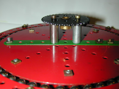
The picture below shows the top of the machine with the main crank in position. It is bolted to the frame members by four 1 1/8" bolts with collars and washers as spacers as required to align the 2" driving sprocket with the sprocket on the third difference axis.
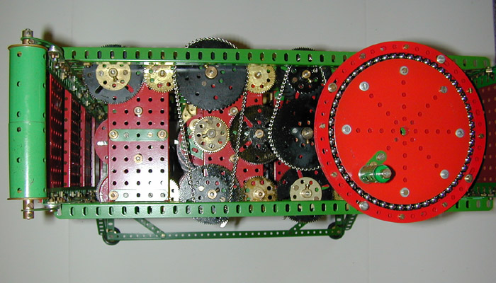
Construction of the crank itself is straight forward. It consists of two 6" circular plates spaced apart with collars and Electrikit thin washers in eight places, and a pair of 7½" circular strips similarly spaced in 12 places, four of these being the mounting bolts to the frame. The space between the circular plates and the circular strips is filled with 3/8" balls, a task which will prove very frustrating to accomplish! On the top side a handle is formed from a sleeve piece mounted on a pair of chimney adapters, a ¾" washer preventing it from being able to slip down. The rod carrying the handle is fixed in a crank on the top side and protrudes through into a 5½" strip bolted on the underside to provide a round hole.
 |
 |
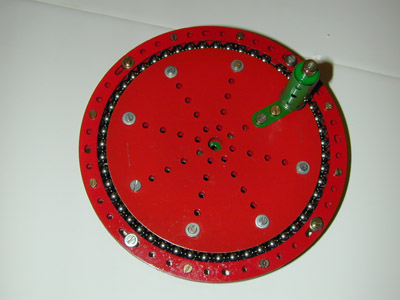
| The
view to the right shows a somewhat clearer view of the mounting of the
main drive sprocket. Electrikit 1"
round cores are used as spacers. When the crank is first assembled, it should be fairly tight to turn. Lubricate the balls well. After some use it should bed in and operate smoothly. |
 |
Framework
> Arrangement of axes and drive system
Decimal digit storage
Digit readout and addition
Carry detection and propagation
Setup and adjustment
Operation
Parts list
Last modified: 23 July 2004 If you experience any problems with this site, please contact the webmaster |
©
2003, 2004 Tim Robinson |