Frontlash Unit
Backlash is a problem in any mechanical system. In the differential analyzer, where variables are represented by the angular motion of interconnected shafts, backlash translates directly into errors in the computed results. In the first differential analyzer, Bush introduced something he called a "frontlash" unit. This was a device, based on an epicyclic gearbox, which could be placed in line in the interconnect to compensate for backlash to first order. It operates by providing a little extra motion at the output compared to the input for a short period following any change in direction of rotation of the input, thereby largely canceling the effects of backlash in the gear train.
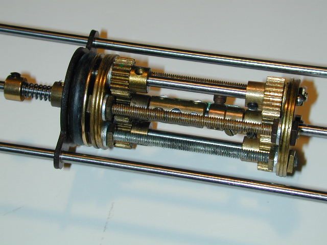
Input and output shafts are collinear. At the left is a friction clutch formed using an Electrikit commutator
which prevents rotation of the cage immediately following a direction reversal of the input. (The outer shafts are unrelated except to provide an anchor for the commutator.) Two stages of 20:19 pinions are used which provide an output approximately 10% faster than the input. However, relative motion of the input an output shafts is limited to the amount of backlash to be compensated. Once this much relative motion has occurred, the input and output are locked together 1:1 and the cage rotates against the friction clutch.
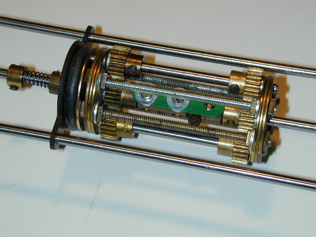
In the view above the stop mechanism can be seen. The narrow strip is fixed to one shaft and the other shaft carries two collars fitted with set screws which can be adjusted to provide the required amount of motion between input and output.
In practice the 19t and 20t pinions do not mesh very well together and it is difficult top make it sufficiently rigid so as not to deflect under heavy load. As a result, the device is very lossy which significantly increases the load on whatever unit (typically an integrator) is driving the input.
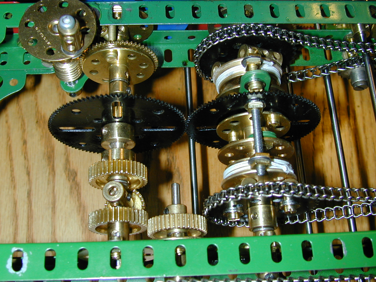
I have found a better solution is to use a differential based design, and to place it between the stages of a two-stage torque amplifier. Placing it there means it operates under very low torque and is much more effective. In particular it imposes almost zero additional load on the output stage of the amplifier. It can be seen at the upper left of this picture of the torque amplifier. The 3" pulley feeds back a small amount of the output to the cage of the differential. Motion of the cage is limited and can be set and adjusted with the hand crank. Once the stop is reached a light friction clutch in the feed from the amplifier output slips so that a 1:1 drive results.

The picture below shows the frontlash stage in more detail, feeding into the input of the second stage of the amplifier.
Last modified: 13 February 2005 If you experience any problems with this site, please contact the webmaster |
©
2005 Tim Robinson |