Torque Amplifiers
My current two-stage design incorporates a frontlash unit in the form of a differential between the two stages of the amplifier. Placing the frontlash unit there, rather than in the interconnect has the advantage that it operates at very low torque, since it is followed by the second stage of the amplifier. This allows it to be of light construction and yet operate smoothly.

The drums in this amplifier are 1 1/8" flanged wheels bolted by couplings to the driving sprockets. It's important that the treads of these wheels be parallel as otherwise the belts will slip down any taper. I have used solid brass reproduction parts from Ashok Banerjee which are very accurately made. It's possible that some pre-war original parts may be good enough, but later production originals are unlikely to work very well. The belts are Dacron cord, 20lb. on the first stage and 75lb. on the second stage. It's important the belts do not expand or contract significantly when they heat up under load. Dacron performs very well in this regard and is very hard wearing. A little dry silicone lubricant on the drums makes for smooth running. It's imperative no oil gets on the surface of the drums or belts, yet at the same time the rods and bearings must be well lubricated to prevent seizing.
Below is a close-up of the input stage.
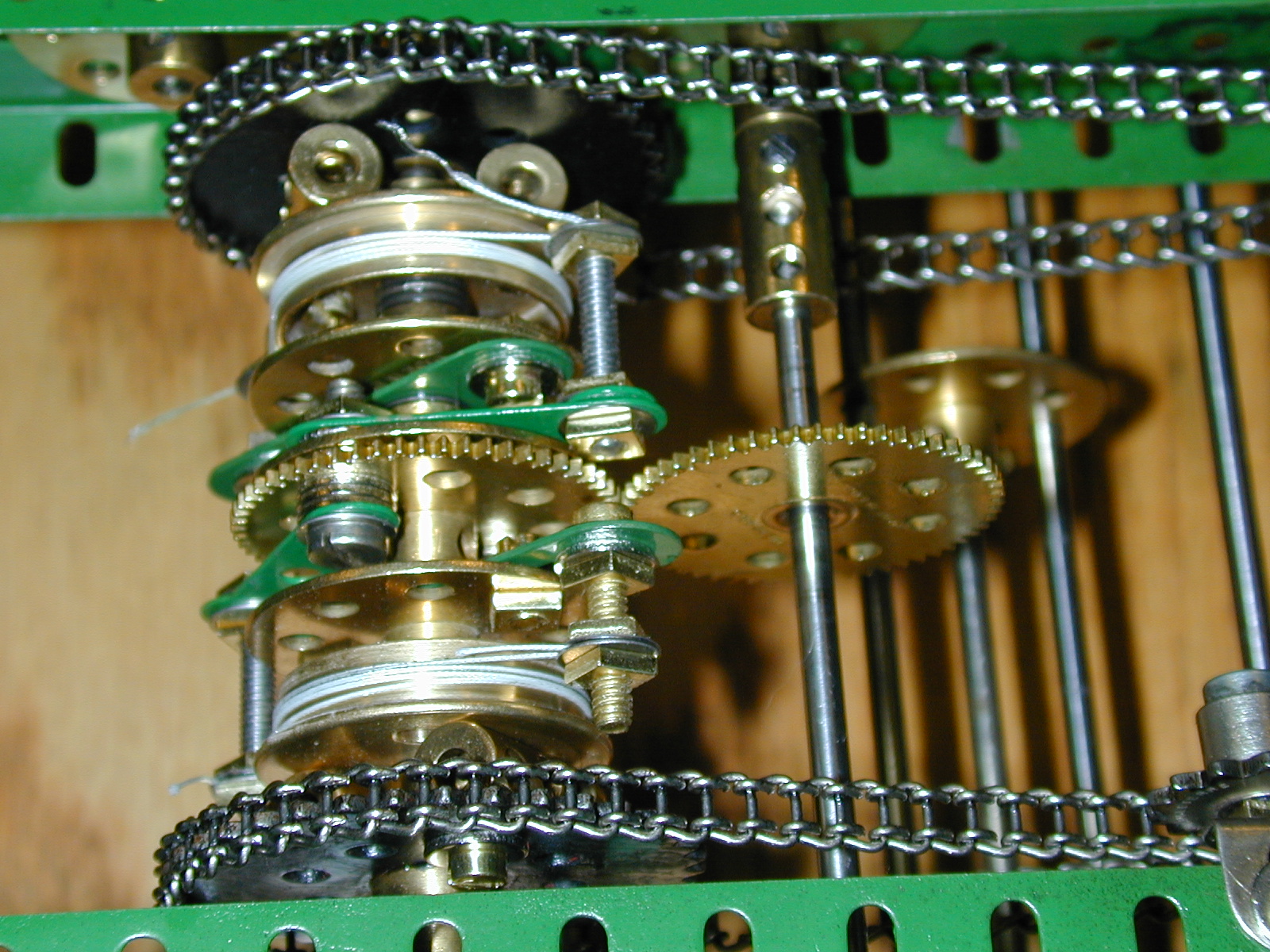
The frontlash unit and second stage can be seen here. The amount of compensation in the frontlash unit can be set finely by the crank and worm drive to a gear which provides one of the stops. The differential is of the "inside out" variety which allows a single continuous shaft to be used. The 1" gears have considerably less backlash than with smaller pinions.
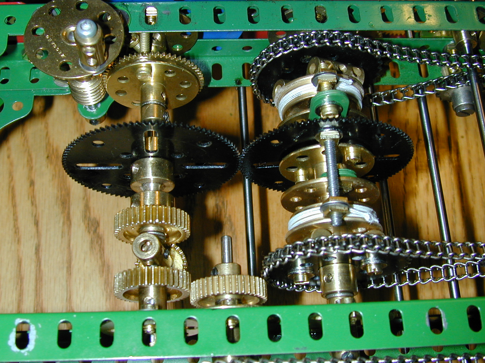
Below is a slightly earlier design with a variant of the frontlash unit. A rather inelegant idler gear was necessary to get the direction of the output to be the same as the input, which is necessary for the zero friction bearing for the input shaft. The idler and small diameter pinions in the differential introduced a lot of backlash. Although this is compensated by the frontlash unit itself, it tended to create instability in the output. The newer design (above) has corrected this.

For a long time I favored a design which used only a single pair of drums and yet was nevertheless a two-stage unit. If you look closely at the pictures below you will see two belts on each drum. The intermediate arms of the amplifier are attached to two face plates which are connected together but free to turn on the output shaft. Between them is a 2½" gear with the input arms. The connection between the intermediate arms is by four reversed angle brackets which pass through the slots of the gear! The drums are boiler ends of the early type which have no holes in the periphery. These are attached to the driving sprockets by locknutted bolts with a 1" rubber ring trapped between to handle the convex surface of the boiler end. The input shaft is missing in this picture but it would have carried another 2½" gear to mesh with the one carrying the input arms. The use of two motors avoided the need of a pair of gears to get the contra rotation of the drums.
Although a clever and compact design, the drums are very hard to make run true and the complexity of the intermediate arm assemblies reduces the rigidity. These units were always temperamental.

A close up shot of the drums and arm assemblies. Note the substantial construction of the output arms, each using two bushwheels and four 2" slotted strips. The input and intermediate arms have balancing weights added.

An earlier version of this design is below. It is more compact, but the output arms are two flimsy and tend to deflect under heavy load. As before the input shaft and driving gear are not present in this picture.

In this close-up of the drum and arm assemblies, the black color on the bands is from powdered graphite used as a lubricant. I later switched to a dry silicone lubricant which is much cleaner.

An even earlier version, this time using wheel flanges as the drums. The belts for the two stages are kept apart by an intervening face plate without boss. The drive on this unit is entirely by belts. While very quite, this proved a problem because the second stage belts, despite being doubled would slip under load.

In this detailed view, note the altogether more flimsy construction compared to later versions above. The connection between the intermediate arms is by a pair of 1" double brackets. The driving bands on the drums are to prevent the belts from falling into the gap between the curved edge of the wheel flange and the face plate.

Below is the earliest single-stage design I have recorded on film, and the first which used the idea of mounting both drums on the output shaft to get round the issue of not having concentric shafting in the Meccano system. The bracing of the framework is overkill compared to the lightweight construction of the arms. While this model worked well as a demonstration unit it was nowhere near robust enough for use in a real differential analyzer. The drive to the drums is entirely through gears, which made it extremely noisy in operation.

Detail of the drums and arms. The drums are boiler ends sandwiched between wheel flanges. In my early designs I felt it was necessary to have an edge to the drums to prevent the belts being able to slip off in operation. As you can see from most of the later designs above, this is completely unnecessary so long as the drums run true and the construction is substantial enough that nothing deflects under load. The limited spacing between the input and output shafts when using 1½" gears made it difficult to construct robust arms in this model. I even had to resort to using shouldered bolts to attach the rod and strip connectors!

Sadly all my earlier designs are now lost. Some more detailed though now rather dated notes, in pdf format, can be found here.
Last modified: 11 December 2004 If you experience any problems with this site, please contact the webmaster |
© 2004 Tim Robinson |